AD9850 - 40MHZ DDS
I recently purchased a small DDS board from ebay for $5 for use in a future project, I’d also seen on the internet a frequency counting library for the arduino and thought this the perfect time put the two together, just to see how they both worked.
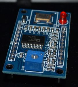
The DDS takes a 40 bit configuration word, which sets both the frequency and the phase, this can either be clocked in serially, or a 5 8 but words. I opted for the serial option, though laziness of not wanting to connect a bunch more wires. The module I’d purchased has a slight discrepancy compared to the Analog Devices data sheet, on the board the analogue output is labelled as ZOUT and ZOUT2, rather than the IOUT and IOUTB.
The frequency counting library is that of Martin Narwth, http://interface.khm.de/index.php/lab/experiments/arduino-frequency-counter-library/, although I first come across it through the frequency counter project of Todd Harrison.
To initialize the DDS a single pulse on each of the RESET, W_CLK and FQ_UD pins is all that’s required before you can start clocking in your desired frequency.
The first 4 bytes of the control word contain the frequency, with the last byte contain control bits and the phase, as i wasn’t terribly interested in the phase of the wave generated I just set this to 0 every time.
The 4 bytes for the frequency are calculated as follows:
fword = freq * 2^32/CLKIN
Where CLKIN in this case is 125MHz
I did notice that the accuracy of the frequency counter on the arduino varied wildly depending on the gate time used, the website for the library states that 10, 100, or a 1000 ms can be used, however I found this lead to the output being a factor of either 100 or 10 out if 10 and 100ms were used respectively, hence I went for the 1000ms gate time.
When measuring the frequency being generated by the DDS I found the arduino consistently gave my 10,006Hz instead of the 10KHz I asked it to generate, although until I get access to a properly calibrated frequency generator I don’t know which is at fault.
Here’s the sketch I used, it’s similar to the example provided with the frequency counter, with ust the DDS control added in:
#include <FreqCounter.h>
#define pulseHigh(pin) {digitalWrite(pin, HIGH); digitalWrite(pin, LOW); }
unsigned long frq;
int cnt;
int pinLed=13;
int pinRESET=4;
int pinFU=3;
int pinWCLK=2;
int pinD7=6;
void sendFreq(double freq) {
 int32_t f = freq * 4294967295/125000000;
 for (int b=0; b<4; b++, f>>=8) {
 tfr_byte(f & 0xFF);
 }
tfr_byte(0x000);
pulseHigh(pinFU);
}
void tfr_byte(byte data) {
 for (int i =0; i < 8; i++, data >>=1) {
 digitalWrite(pinD7, data & 0x01);
 pulseHigh(pinWCLK);
 }
}
void init_dds() {
 pinMode(pinRESET, OUTPUT);
 pinMode(pinFU, OUTPUT);
 pinMode(pinWCLK, OUTPUT);
 pinMode(pinD7, OUTPUT);

 digitalWrite(pinRESET, LOW);
 digitalWrite(pinWCLK, LOW);
 digitalWrite(pinD7, LOW);
 digitalWrite(pinFU, LOW);

 pulseHigh(pinRESET);
 pulseHigh(pinWCLK);
 pulseHigh(pinFU);

}
void setup() {
 pinMode(pinLed, OUTPUT);
 init_dds();
 Serial.begin(115200); // connect to the serial port
 sendFreq(10000);
 Serial.println("Frequency Counter");

}
void loop() {

 // wait if any serial is going on
 FreqCounter::f_comp=6; // Cal Value / Calibrate with professional Freq Counter
 FreqCounter::start(1000); // 1000 ms Gate Time
while (FreqCounter::f_ready == 0)
 //sendFreq(cnt);
 delay(10);
 frq=FreqCounter::f_freq;
 Serial.print(cnt++);
 Serial.print(" Freq: ");
 Serial.println(frq);
 delay(20);
 digitalWrite(pinLed,!digitalRead(pinLed)); // blink Led
}